Measuring pulse length and speed Encoder ENC-1-1-T-24 is an important process in many industrial applications, especially in automation and control systems. To do this accurately and effectively, the use of a specialized meter such as the LC6-P62NA is necessary. In this article, we will show you in detail how to measure the length and speed of the Encoder ENC-1-1-T-24 pulse with the LC6-P62NA meter, helping you grasp and apply measurement techniques easily. the most accurate way. Through this, you will be able to optimize the performance and accuracy of your automation system during production.
I. Overview of Hanyoung LC6-P62NA Counter / Timer and Encoder ENC-1-1-T-24
LC6-P62NA Counter/Timer
Specifications:
• Power voltage: 100-240Vac
• Operating frequency: 50-60Hz
• Power consumption: Max 12VA
• Display digits: 6 digits (999999)
• Max counting speed: 1cps/30cps/1 Kcps/10Kcps
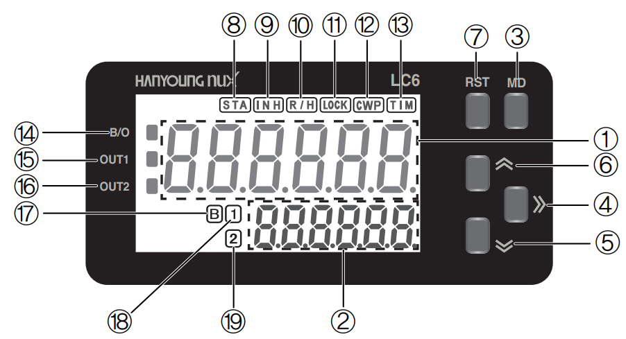
Main interface:

1: PV display: displays count value, time value, batch count value, setting item.
2: SV display: displays the setting value.
3: MODE key: enter and exit function mode (automatically save function set value while finishing): used to switch SV display in operation mode.
4: >> key: enter set value change mode and change the set value digits, enter communication setting mode in function mode.
5: Down arrow key: decrease the value set in function mode and set value change mode.
6: Up arrow key: increase the value set in function mode and set value change mode.
7: RST (Reset) key: Reset count value, time value and output status.
8: START input indicator: lights when the external START signal is applied in timer operation mode.
9: INHIBIT input indicator: lights when the external INHIBIT signal is applied in timer operation mode.
10: RESET input indicator: lights up when an external RESET signal is applied.
11: LOCK set indicator: lights up when LOCK is set.
12: Communication write inhibition indicator: lights up when communication write inhibition is set.
13: Timer setting indicator: lights up when TIM/TTIM/BTIM operation mode is set, flashes during timing operation.
14: BATCH output indicator: lights up during BATCH output operation.
15: OUT1 output indicator: lights up during OUT1 output operation.
16: OUT2 output indicator: lights up during OUT2 output operation.
17: BATCH setting indicator: lights up when switching the SV display to the BATCH set value.
18: OUT1 setting indicator: lights up when the SV display switches to setting value 1.
19: OUT2 setting indicator: lights up when SV display switches to setting value 2.
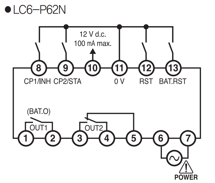
Pinout:

• Pins 1,2: OUT1 output (BATCH output)
• Pin 3,4,5: OUT2 output (NO: pin 3,5 and NC: pin 4,5)
• Pin 6,7: 220VAC power supply
• Pin 8: CP1/INH input
• Pin 9: CP2/STA input
• Pin 10: 12VDC power supply, max current 100mA
• Pin 11: 0V ground pin
• Pin 12: external reset pin (RST)
• Pin 13: BATCH reset pin
Operating mode:
Display | Operating mode | Describe |

| Preset Counter | According to input mode, it adds, subtracts, adds/subtracts and counts pulses applied to external input CP1/CP2. When the count value reaches the 1 and 2 stage set values, OUT1 and OUT2 are operated according to the selected output mode. |

| Batch Counter | The batch output is enabled when the batch count value reaches the batch set value, after counting the counter counts. |

| Timer | When a signal is applied to the external input START/INHIBIT/RESET, the operating time is displayed according to the time range. OUT1 and OUT2 outputs are operated according to the selected output mode when the time value reaches the 1 and 2 stage set values. |

| Twin Timer | OUT1 and OUT2 outputs are turned ON/OFF according to ON and OFF setting times. (OUT output is operated in 1-phase model, OUT1 and OUT2 outputs are operated simultaneously in 2-phase model). |

| Batch Timer | The batch output is activated when the batch count value reaches the batch set value, after the timer counts. |
Other parameters:
- Communication function mode:
Display | Meaning | Parameters |

| Communication address | 
|

| Communication speed | 
|

| Communication parity bit | 
|

| Response waiting time | 
|

| Record communication value | 
|
Functions in Counter mode:
Display | Meaning | Parameters |

| Input mode | 
|

| Output mode | 
|

| OUT2 output time | 
|

| OUT1 output time | 
|

| Counting speed | 
|

| Scale decimal point | 
|

| Ratio | 
|

| Decimal point | 
|

| Reset time | 
|

| Save value when power is lost | 
|

| Logical input | 
|

| Key lock | 
|

| Offset | 
|
Autonics ENC-1-1-T-24 rotary encoder
Specifications
- Maximum response frequency: 180kHz
Maximum allowable resolution: 5000rpm
Output phase: A,B
Wheel diameter: 250mm
Minimum measurement unit: 1mm
Gear ratio: 1:1
Number of pulses: 250
Control output: Totem pole
Power supply: 12-24VDC ±5%(P-P wave: max. 5%)
Connection type: Axial cable type
Protection structure: IP50
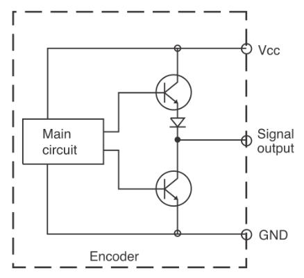
Totem Pole output

Totem Pole circuit:

- Includes two NPN transistors located between the Vcc source, the Encoder output circuit and 0V.
If one transistor is ON, the other will be OFF.
Current enters in both directions through the two transistors of the output side, and output current flows all the time. Therefore it has low impedance and is not much affected by noise and distortion waves.
This circuit can be used as a replacement for Voltage Output and Open Collector type Encoder outputs. - Output wave:
- The direction of rotation is based on the direction of rotation towards the axis and clockwise (CW) when rotating to the right.
Phase difference between phases A and B: T4T8 (T is the period of A)

Encoder pin diagram:

Note:
- Unused wires must be insulated.
The Encoder's metal case and shift cable must be grounded (F.G).
F.G wire must be grounded separately. - Advantages and features:
- Wheel type rotary encoders are used to measure the length or continuously moving speed of an object.
The output wave of the measured distance is proportional to the International Weight/Measurement (meters/inches).
Power supply: 5 VDC ±5%, 12-24 VDC ±5%. - Application:
The Autonics ENC-1-1-T-24 relative rotation converter is commonly used in:
The ENC series relative rotary encoders are the ideal choice for measuring the length or speed of continuously moving objects.
ENC series can be used in embroidery machines, automation machines, blow molding machines, sheet rolling machines, aluminum bar cutting machines, printing machines, packaging machines, etc.
II. Instructions for measuring Encoder ENC-1-1-T-24 pulse length and speed with LC6-P62NA meter
Connection diagramParameter setting steps
Step 1: Select the operating mode as Counter ( )
)
Step 2: Select input mode as Ud-C

Step 3: Select the output mode as C
When the count value reaches the set value, the displayed count continuously increases or decreases after initialization. OUT2 output will turn off after outputting one shot for the set time. The self-hold output of OUT1 turns off together with the OUT2 output. OUT1's one-shot output will turn off after OUT1 output setting time, regardless of OUT2 output. Count value, display value and output are initialized during input reset.
Step 4: Set OUT2 output time to 1 second
Step 5: Set OUT1 output time to 5 seconds
Step 6: Select a count rate (CPS) of 10K and leave the prescale decimal point intact ( )
)
Step 7:
Set the scale value ( ) is 001,000 to measure the number of pulses of the encoder and use the encoder to measure the length.
The number of pulses displayed on the clock is 250 when the encoder is rotated 1 cycle.
Gear diameter is D = 80mm.
How to calculate length per pulse:
We have:

That is: the clock displays 300 pulses, the object will have a length of 300 (mm).
Set the scale value ( ) is 000.004 so that the clock counts up 1 pulse when the encoder gear rotates 1 revolution.
The meter displays 250 pulses when turning the gear 1 revolution.
Therefore the proportional value is: 
Step 8: Leave the decimal point intact ( ) default and set the reset time to 1 ms. Select Save in the function
  To save values when power is lost, the remaining functions keep the parameters as default.
III. Video tutorial on how to measure Encoder ENC-1-1-T-24 pulse length and speed with LC6-P62NA meter
In case you want to learn, need technical advice and order the Encoder ENC-1-1-T-24 and the LC6-P62NA Timer/Counter , please contact Amazen immediately via:
Hotline: 0934 399 068 - Sales: 0938 072 058
Email: amazen@amazen.com.vn
With a highly specialized technical support and sales consulting team, our company is confident that it will bring customers the best purchasing experience.
Amazen commits that all inverter products we currently offer are genuine, 100% brand new, quality guaranteed and complete with CO/CQ and VAT certification documents accompanied.